
- Position:
- Batte Melt pump > NEWS >

Reasons and Countermeasures of Melt Pump Coupling Tripping
The melt pump is the discharge pump of the final polymerization reactor, and it is the power equipment for the polyester plant to deliver the melt to the downstream short fiber and filament plant, and it is one of the key equipment of the polyester plant. However, 10 months after the start of the polyester plant, the coupling of the melt pump has been tripped for many times, causing the product quality of the plant to fluctuate greatly and causing huge economic losses to the enterprise. This paper makes a comprehensive analysis of the factors that affect the tripping of the melt gear pump coupling, and proposes corresponding solutions.
1 How the melt pump works
The gear pump relies on the change of the working space volume caused by the mutual meshing of the gears to transport the liquid. The working space is composed of the pump body, the side cover and the inter-tooth grooves of the gears. The teeth of the meshing part are shown as ABC in Figure 1. They divide the space into a suction chamber and a discharge chamber. When a pair of gears rotate in a certain direction, the teeth located in the suction cavity gradually withdraw from meshing, so that the volume of the suction cavity gradually increases, the pressure decreases, and the liquid enters the suction cavity along the suction pipe until it fills the teeth. , the liquid is brought into the discharge chamber and forced to the outlet of the pump into the pipeline. Inlet pressure: 8~15kPa; Motor speed: 145~1450r/min; Outlet pressure: 17MPa; Motor power: 170kW; Operating temperature: 292℃; Design flow: 12.6t/h.
2 Reasons for melt pump coupling tripping
By analyzing the actual situation of the multiple coupling tripping of the melt pump, we believe that the reasons for this phenomenon are as follows.
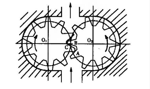
Working principle diagram of melt gear pump
2.1 The melt pump load is too high
So far, when all melt pump coupling tripping occurs, the melt pump load is above the design load!!#K. At the same time, compared with other polyester devices of DuPont process, only our factory arranges the melt cooler after the melt pump in the design, and the melt coolers of other manufacturers are all arranged after the spinning booster pump. Therefore, the outlet pressure of the melt pump rises by about *GB<, which increases the load and torque of the melt pump. At this time, the melt pump speed exceeds $0=CDEF, and its design speed is only $(-0=CDEF. The melt pump and the coupling work in a critical state for a long time. Once there is load fluctuation or foreign matter jamming, the instantaneous A sudden increase in torque will make the coupling easier to trip.
2.2 The melt solidifies at the shaft seal
The melt pump seal adopts the combined structure of reverse screw seal and packing seal, and uses cooling water to cool the shaft seal. It adopts melt self-lubricating, and leads the melt to the seal at the outlet of the melt pump and returns to the inlet side of the pump In this way, while lubricating the lubricating parts, it also ensures that the shaft seal has a certain pressure to prevent the outside air from entering the vacuum reaction system. In actual operation, the pump requires that the shaft seal must maintain a micro-leakage state. This can not only avoid the increase of friction and torque caused by the condensation of the melt at the shaft seal, but also avoid the potential safety hazard caused by the leakage of a large amount of melt, the decrease of the efficiency of the melt pump, and the increase of the actual load.
In actual operation, since the leakage of the shaft seal is controlled by the cooling water valve, it is possible that the melt at the shaft seal will be completely cooled and solidified due to changes in the temperature, pressure and flow of the cooling water, resulting in an increase in the rotational torque of the pump and the coupling of the shaft. Section trips.
2.3 Foreign objects stuck in the pump
2.3.1 Condensate on the inner wall of gas pipeline
From the lumps on the other side of the gas phase pipeline scraped by the mechanical probe, it can be inferred that the same lumpy high-viscosity materials or hard lumps due to cold spots may also be produced on the side of the gas phase pipeline in the finalizer. When these materials enter the melt pump, a large resistance will be formed in the pump, causing the coupling to trip.
2.3.2 The inner leakage of the mechanical seal of the final polymerization kettle forms a hard block
The finalization vessel was mechanically sealed with double end faces, flushed and sealed with fresh EG. At present, the machine seal has been found to be leaking. If the seal has internal leakage at the same time, it is possible to produce local cold spots and form hard lumps. When the hard block enters the pump body, it will also cause the tripping of the coupling.
2.3.3 Hard particles entering the system
The materials entering the final polymerization tank can be divided into % parts, and a part is the main material, that is, the slurry enters the final polymerization tank through the esterification system and the pre-polycondensation system. After this part of the material passes through the slurry filter and the oligomer gear pump, it is difficult for impurity particles to enter. The other part is additives. Among the 4 additives, titanium dioxide and catalyst are strictly filtered during the configuration process, and the injection system is a closed system, which will not bring impurities into the system. The addition and injection containers of DEG are open containers at atmospheric pressure, and foreign matter may enter the system. As a result, the gears in the pump may be blocked and the coupling may be tripped.

2.4 The load fluctuates greatly
In actual production, accidents such as the tripping of the downstream booster pump often occur with large fluctuations in load. At this time, the melt pump will rapidly and greatly reduce the speed under automatic control, and when the booster pump recovers rapidly, the melt The pump will increase the speed rapidly. During this process, the torque of the melt pump fluctuates greatly, which can easily cause the coupling to trip. This has been the case in accidents that have occurred.
2.5 Quality defects of the coupling itself
In order to verify the quality of the coupling itself, we carried out a thorough disassembly inspection of the replaced coupling and found no quality problems.
3 Precautions
In order to ensure the normal operation of the melt pump and avoid the recurrence of the coupling tripping accident, we have formulated the following preventive measures through careful analysis and research of the situation.
3.1 Working conditions of stable melt pump
Melt pump torque calculation formula:

Among them: M is the input torque (working torque), Nm; △P is the pressure difference between the inlet and outlet of the pump, MPa; ηn is the mechanical efficiency of the melt pump; q is the displacement of the pump, that is, the mass of the melt discharged by the gear pump per revolution.
We can see that when the mechanical efficiency of the melt pump remains unchanged, the working torque of the melt pump is proportional to the pressure difference between the pump inlet and outlet. Properly reducing the melt pump outlet pressure will help reduce the melt pump torque. Therefore, we improved the switching standard of the rear melt filter, and at the same time appropriately reduced the melt line pressure, so that the melt pump outlet pressure was reduced to below 16.8MPa, so that the melt pump speed and torque were reduced, far from the critical point.
3.2 Strengthen on-site inspection
After the melt pump coupling has tripped, we immediately designated it as special protection equipment. Operators, managers and maintenance personnel will check and record it carefully every day, especially the shaft seal. The leakage of the seal is too large or there is no leakage to avoid the coupling tripping caused by this.
3.3 Strengthen the management of additive configuration
We have improved the feeding system of DEG, adding a filter link during the feeding process, and sealing the feeding port with a cover plate immediately after the feeding is completed to prevent impurity particles from entering the system.

3.4 Strengthen process monitoring
3.4.1 Strengthen the monitoring of temperature
By monitoring the temperature of the final polymerization kettle or the gas phase pipeline and the body of the melt pump, it can be found whether there is uneven heating inside the equipment, so as to eliminate and avoid the appearance of cold spots, and prevent the generated hard blocks from entering the pump and causing the coupling to break off. buckle.
3.4.2 Strengthen the monitoring of viscosity
We reduced the deviation range of the viscosity control index from ±4 to ±2 to reduce the fluctuation of viscosity, stabilize the working condition of the melt pump, and reduce the torque fluctuation caused by the influence of viscosity.
3.4.3 Strengthen the monitoring of cooling water
By strengthening the monitoring of the temperature and pressure of the shaft seal cooling water, abnormal changes in the cooling water can be found in time to avoid the resulting influence on the shaft seal cooling effect.
3.5 Increase the training of operators
Enhancing the operator's ability to deal with emergencies, especially the reaction speed and handling method after the rear booster pump trips, will greatly reduce the resulting melt pump coupling shedding phenomenon. At the same time, through training, the deficiencies of some personnel in operating methods have been corrected, and human errors, such as lifting and lowering the load too quickly, have been reduced to a great extent. info@battemachinery.com

Any questions about our products, please feel free to contact us! We promise you high-end products and first-class service.Look forward to our cooperation!!!
- sales@battemachinery.com
- +0086-371-67991755


